Thermal Cycling Equipment in Solar Panel Durability Testing
Solar panels endure relentless temperature swings throughout their 25-to-30-year service life - baking under midday sun, then cooling sharply after sunset. Thermal cycling equipment replicates these punishing fluctuations inside a controlled laboratory environment, subjecting photovoltaic (PV) modules to repeated temperature ramps between extremes such as -40°C and +85°C. This accelerated stress exposes latent weaknesses in solder ribbons, encapsulant layers, glass-cell interfaces, and electrical connections long before panels reach rooftops. By compressing years of field exposure into weeks of laboratory testing, engineers gain the failure-mode data needed to refine materials, optimize manufacturing processes, and validate the long-term power output warranties that underpin investor confidence in solar energy projects worldwide.

A leading electronics testing lab shared their experience with our THR10-500A Thermal cycling equipmentand drying ovens: "Our THR10-500A chamber and drying ovens are working excellently, thank you. We are very happy with them." The stable performance of the chamber during intensive thermal cycling tests enabled the team to conduct extended burn-in procedures and repeated rapid temperature transitions without interruption. This reliability gave them confidence in accurately assessing the thermal resilience and durability of automotive electronics, sensors, and control modules. Beyond electronics, the equipment has proven highly effective in materials testing, plastic component aging, and battery performance evaluations, helping teams efficiently simulate real-world thermal conditions and optimize product longevity.
Why Solar Panels Require Thermal Cycling Testing?

 Decades of Outdoor Exposure and Temperature Extremes
A rooftop or ground-mounted solar array faces unshielded exposure to seasonal extremes - scorching summers, freezing winters, and everything between. Desert installations experience daily temperature differentials exceeding 50°C, while Nordic sites endure prolonged sub-zero conditions. Over a 25-year warranty period, a single panel can accumulate tens of thousands of thermal cycles, each one incrementally stressing internal interfaces and interconnects.
Cumulative Fatigue Mechanisms in PV Modules
Each temperature swing induces micro-scale expansion and contraction across dissimilar materials bonded together inside the module laminate. Fatigue cracks nucleate at stress concentration points - particularly solder joints connecting silicon cells to copper ribbons - and propagate cycle after cycle. Without thermal cycling evaluation, these slow-growing defects escape detection during routine electrical inspection at the factory gate.
Economic Stakes of Premature Panel Degradation
Solar project economics depend on predictable energy yield over decades. A module that degrades faster than warranted erodes investor returns, triggers warranty claims, and damages manufacturer reputation. Rigorous thermal cycling qualification using purpose-built test chambers catches vulnerable designs early, allowing corrections that safeguard both revenue streams and brand equity.
Temperature Stress in Photovoltaic Modules and Materials
CTE Mismatch Across Multi-Layer Module Stacks
Solar modules are laminated sandwiches - tempered glass, ethylene-vinyl acetate (EVA) encapsulant, silicon cells with metallic interconnects, a polymeric backsheet, and an aluminum frame. Each layer possesses a distinct coefficient of thermal expansion (CTE). When temperature changes, these layers stretch or contract at different rates, generating shear and peel stresses at every bonded interface.
Table 1: CTE Values of Common PV Module Materials
|
Material |
Approximate CTE (ppm/°C) |
Role in Module |
|
Tempered glass |
8-9 |
Front cover |
|
EVA encapsulant |
150-200 |
Cell encapsulation |
|
Crystalline silicon cell |
2.6 |
Power generation |
|
Copper ribbon |
17 |
Cell-to-cell interconnect |
|
PET/PVF backsheet |
20-80 |
Rear moisture barrier |
|
Aluminum frame |
23 |
Structural support |
Thermomechanical Strain at Cell Interconnects
The CTE disparity between silicon (2.6 ppm/°C) and copper ribbon (17 ppm/°C) concentrates cyclic strain directly at the solder bond line. Repeated bending fatigues the solder alloy, nucleating cracks that increase series resistance and reduce power output. Thermal cycling chambers apply controlled ramp rates - typically 5°C to 15°C per minute - to replicate this strain accumulation under laboratory conditions.
Encapsulant and Backsheet Degradation Under Cyclic Stress
EVA and other encapsulants soften at elevated temperatures and stiffen at low temperatures during testing in a thermal cycling test chamber. Cycling between these states can initiate delamination from the cell surface or from the glass superstrate, creating pathways for moisture ingress. Backsheet polymers undergo analogous embrittlement, eventually cracking and compromising the module's electrical insulation integrity.
Testing Standards for Solar Panel Thermal Cycling Performance
IEC 61215 Thermal Cycling Requirements
IEC 61215 - the benchmark qualification standard for crystalline silicon PV modules - prescribes a TC200 test: 200 cycles between -40°C and +85°C with a maximum ramp rate and defined dwell times at each extreme. Modules must show no major visual defects, no wet leakage current failures, and no more than 5% maximum power degradation after completing the protocol.
Extended Cycling Protocols Beyond Minimum Qualification
Industry consensus increasingly recognizes that 200 cycles represent a bare minimum. Many manufacturers and independent test laboratories voluntarily extend cycling to TC400, TC600, or even TC1000 to differentiate premium products and satisfy stringent bankability requirements from project financiers. Extended protocols surface wear-out failure modes that shorter tests simply cannot reveal.

![]()
Table 2: Common Solar Panel Thermal Cycling Test Protocols
|
Protocol |
Temperature Range |
Cycle Count |
Ramp Rate |
Key Standard |
|
TC200 |
-40°C to +85°C |
200 |
≤ 100°C/h |
IEC 61215 |
|
TC400 |
-40°C to +85°C |
400 |
≤ 100°C/h |
Extended IEC |
|
TC600 |
-40°C to +85°C |
600 |
≤ 100°C/h |
Extended IEC |
|
Combined TC + HF |
-40°C to +85°C |
200 + 10 HF |
Per spec |
IEC 61215 seq. |
Combining Thermal Cycling with Humidity and Mechanical Load Tests
IEC 61215 also mandates sequential testing - thermal cycling followed by humidity-freeze (HF) cycles and mechanical load tests. This combined sequence mimics the synergistic stresses modules encounter in the field. Thermal cycling equipment capable of precise ramp control and stable dwell temperatures streamlines these sequential campaigns without requiring specimen transfers between separate chambers.
Simulation of Day-Night Temperature Fluctuations in Solar Installations
Programmable Ramp Rates for Realistic Profiles
Real-world solar panels heat and cool at rates governed by solar irradiance, wind speed, and ambient temperature. A controllable ramp rate - selectable at 5°C, 10°C, or 15°C per minute - allows test engineers to tailor profiles that mirror specific geographic conditions. Slower ramps replicate temperate climates; steeper ramps simulate arid environments with abrupt post-sunset cooling.
Dwell Periods and Thermal Equilibrium Considerations
Modules must reach uniform internal temperature before a meaningful thermal cycle is recorded. Dwell times at the hot and cold extremes guarantee that the innermost layers - including the cell-EVA interface - equilibrate fully. Inadequate dwell periods understate the true stress experienced by embedded interconnects, producing misleadingly optimistic qualification results.
Climate-Specific Test Profile Design
A panel destined for the Arabian Peninsula faces a different thermal envelope than one installed in Scandinavia. Engineers design custom cycling profiles - adjusting upper and lower temperature limits, ramp rates, and cycle counts - to replicate the target deployment climate. Programmable controllers with Ethernet connectivity and PC link capability simplify the creation and storage of these bespoke profiles.
Evaluating Glass, Encapsulation Materials, and Electrical Connections
Solder Ribbon Fatigue and Cell Interconnect Integrity
Electroluminescence (EL) imaging before and after testing with thermal cycling test equipment reveals inactive cell areas caused by cracked solder joints. As cracks propagate, series resistance climbs and module fill factor drops. Quantifying this degradation through I-V curve measurements at defined cycle intervals provides a fatigue growth rate that informs solder alloy selection and ribbon geometry optimization.
EVA Yellowing and Delamination Detection
Prolonged thermal cycling accelerates EVA discoloration, particularly in the presence of residual crosslinking byproducts. Yellowed encapsulant absorbs a portion of the incident light spectrum, reducing short-circuit current. Visual inspection, transmittance spectroscopy, and C-mode scanning acoustic microscopy together quantify the extent and progression of encapsulant degradation throughout the cycling campaign.
Junction Box and Connector Reliability Under Cycling
Junction boxes and cable connectors mounted on the module backsheet endure the same thermal excursions as the laminate itself. Solder connections within the junction box, adhesive bonds securing it to the backsheet, and the bypass diode operating temperature all warrant scrutiny. Post-cycling insulation resistance and wet leakage tests confirm that electrical safety margins remain intact.
Improving Long-Term Solar Panel Reliability Through Environmental Testing
Correlating Accelerated Test Data with Field Performance
Acceleration factors - derived from Arrhenius or Coffin-Manson models - translate laboratory cycle counts into equivalent years of field exposure. Validated correlation allows manufacturers to predict real-world degradation rates from chamber test results, bridging the gap between a two-week laboratory campaign and a 25-year performance warranty.
Design Iteration Based on Failure Mode Analysis
Each failure mode uncovered during thermal cycling feeds back into a continuous improvement loop. Solder cracking may prompt a shift to a more fatigue-resistant alloy; delamination may drive adoption of a higher-adhesion encapsulant formulation. This iterative process, grounded in empirical chamber data, progressively hardens the module design against thermomechanical stress.
Building Warranty Confidence Through Rigorous Qualification
Module bankability - the willingness of financial institutions to fund solar projects - hinges on robust qualification evidence. Extended thermal cycling reports from accredited laboratories, generated using calibrated and traceable environmental chambers, furnish the documentation that due-diligence teams demand before committing capital to large-scale photovoltaic installations.
Reliable Performance Under Extreme Temperature Swings - LIB Industry
 |
 |
|||||||
| Name | Fast Change Rate Thermal Cycle Chamber | |||||||
|
Temperature range |
-70℃ ~+150 ℃ |
|||||||
| Explosion-Proof Design | explosion-proof door chains, explosion-proof viewing window, smoke detector, and fire suppression sprinkler system Explosion-proof enclosure | |||||||
|
Low type |
A: -70℃ B:-40℃ C -20℃ |
|||||||
|
Temperature fluctuations |
± 0.5 ℃ |
|||||||
|
Humidity Range |
20%~98% |
|||||||
|
Heating rate |
5 ℃/15 ℃ / min |
|||||||
|
Cooling rate |
5 ℃/15℃ / min |
|||||||
|
Controller |
Programmable color LCD touch screen controller, Multi-language interface, Ethernet , USB |
|||||||
|
Exterior material |
Steel Plate with protective coating |
|||||||
|
Interior material |
SUS304 stainless steel |
|||||||
|
Standard configuration |
1 Cable hole (Φ 50) with plug; 2 shelves |
|||||||
|
Timing Function |
0.1~999.9 (S,M,H) settable |
|||||||
|
|
|
|
| Robust Workroom | Cable Hole | Temperature and Humidity Sensor |


Wide Temperature Range and Controllable Ramp Rates
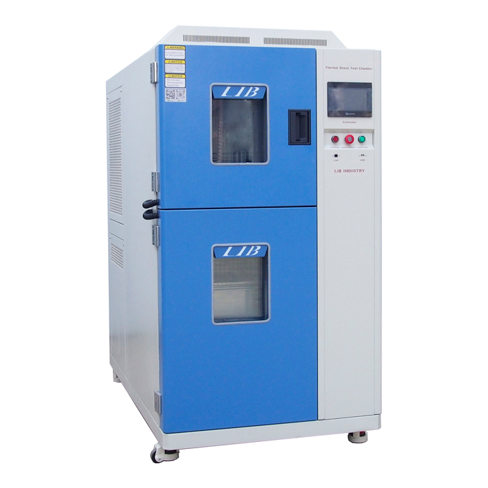
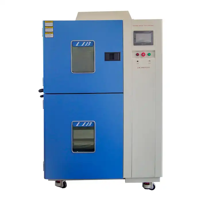
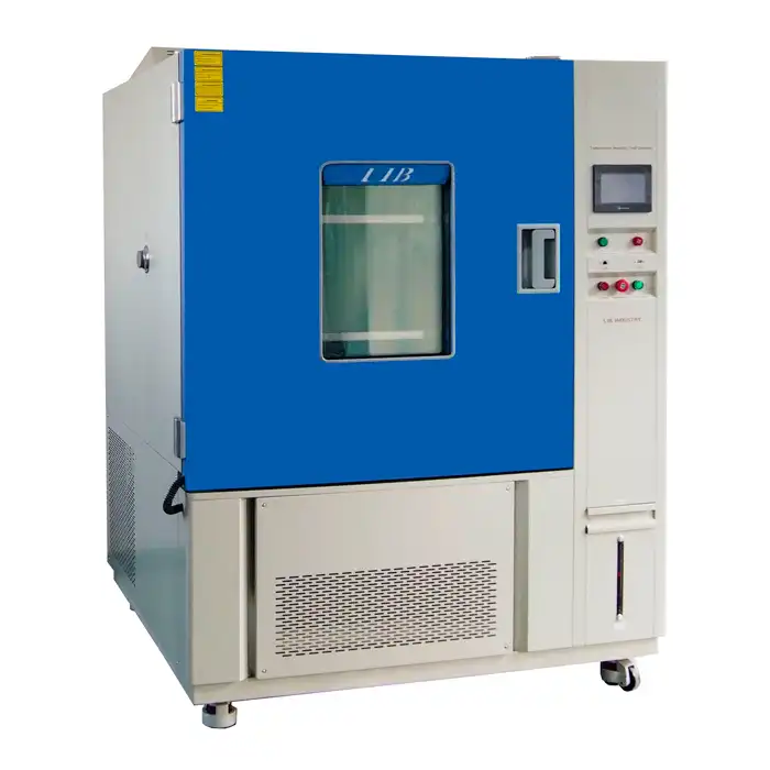
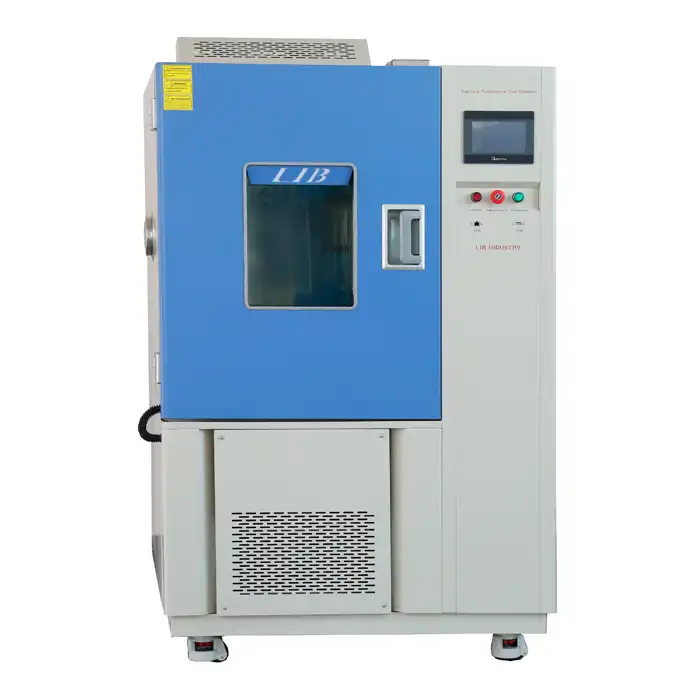
LIB Industry's thermal cycling equipment delivers temperature ranges spanning -70°C to +150°C, comfortably enveloping the -40°C to +85°C window mandated by IEC 61215. Ramp rates are selectable at 5°C, 10°C, or 15°C per minute, enabling engineers to match test profiles to any climate scenario without hardware modifications. Temperature fluctuation is held within ±0.5°C and deviation within ±2.0°C - precision critical for repeatable, standards-compliant results.
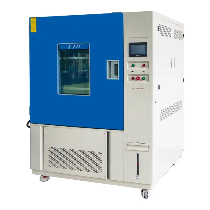
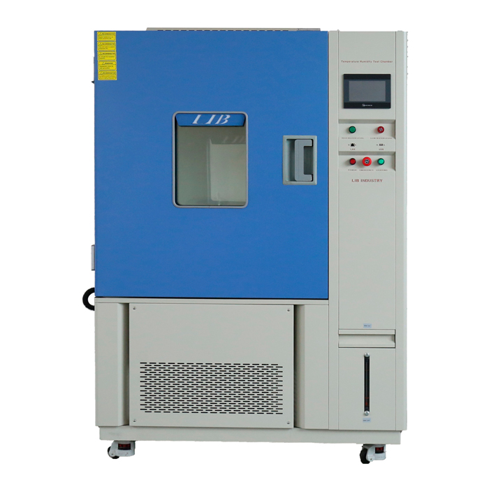
Scalable Chamber Volumes for Full-Size Module Testing
LIB offers volumes from 100 L through 1000 L and beyond - including 2000 L and 3000 L custom configurations - accommodating everything from small material coupons to full-size 72-cell photovoltaic modules.
Safety, Connectivity, and Custom Configurations
Every thermal cycling machine incorporates over-temperature protection, over-current protection, refrigerant high-pressure safeguards, and earth leakage protection. An explosion-proof door and viewing window, smoke detector with buzzer, and water spray system provide additional safety layers. Ethernet-connected programmable LCD touch screen controllers enable remote monitoring and seamless integration with laboratory information management systems. Cable holes (50 mm / 100 mm / 200 mm) with silicone plugs route sensor leads and power cables into the test space without compromising thermal integrity. Custom models addressing unique specimen dimensions or performance specifications are available on request.
Conclusion
Thermal cycling testing stands as a cornerstone of solar panel qualification, revealing the fatigue-driven degradation mechanisms that threaten long-term energy yield. By subjecting modules to thousands of controlled temperature ramps, engineers identify vulnerable solder joints, encapsulant interfaces, and electrical connections before products enter the field. Adherence to IEC 61215 - and increasingly to extended cycling protocols - ensures modules meet the reliability expectations embedded in 25-year performance warranties. Purpose-built thermal cycling equipment with precise ramp control, wide temperature ranges, and scalable volumes empowers PV manufacturers to deliver panels that perform consistently across the planet's most demanding climates.
FAQ
What temperature range does IEC 61215 require for solar panel thermal cycling?
IEC 61215 specifies cycling between -40°C and +85°C. Modules must complete 200 cycles (TC200) and demonstrate no more than 5% maximum power degradation along with no critical visual defects.
Why are extended thermal cycling protocols (TC400, TC600) gaining popularity?
Extended protocols expose wear-out failure modes - such as advanced solder fatigue and encapsulant delamination - that remain undetectable within the standard 200-cycle qualification, satisfying increasingly stringent bankability demands from project financiers.
Can LIB Industry thermal cycling chambers accommodate full-size PV modules?
LIB offers chamber volumes up to 1000 L in standard models and 2000 L or 3000 L in custom configurations, providing ample interior space for full-size 60-cell or 72-cell photovoltaic modules.
Need a dependable thermal cycling equipment manufacturer and supplier for your solar panel testing laboratory? LIB Industry provides turnkey environmental testing solutions - from design and production through installation and training. Reach out at ellen@lib-industry.com to discuss your PV module durability testing needs.

.webq.jpg)