What are the main tests performed in a PV Environmental Chamber?
Photovoltaic modules endure extreme environmental stresses throughout their operational lifespan, making rigorous testing essential for ensuring long-term reliability and performance. A PV environmental chamber provides controlled conditions that accelerate weathering processes, revealing potential failure modes before modules reach commercial deployment. The primary tests performed include temperature cycling, humidity freeze testing, ultraviolet exposure, and salt mist corrosion evaluation - each designed to simulate specific environmental stressors encountered during decades of field operation. LIB Industry manufactures precision-engineered PV environmental chambers featuring robust construction, advanced control systems, and customizable configurations that accommodate diverse panel sizes while delivering reproducible results. These chambers enable manufacturers to validate module durability, satisfy international certification requirements, and optimize design parameters for enhanced field performance.

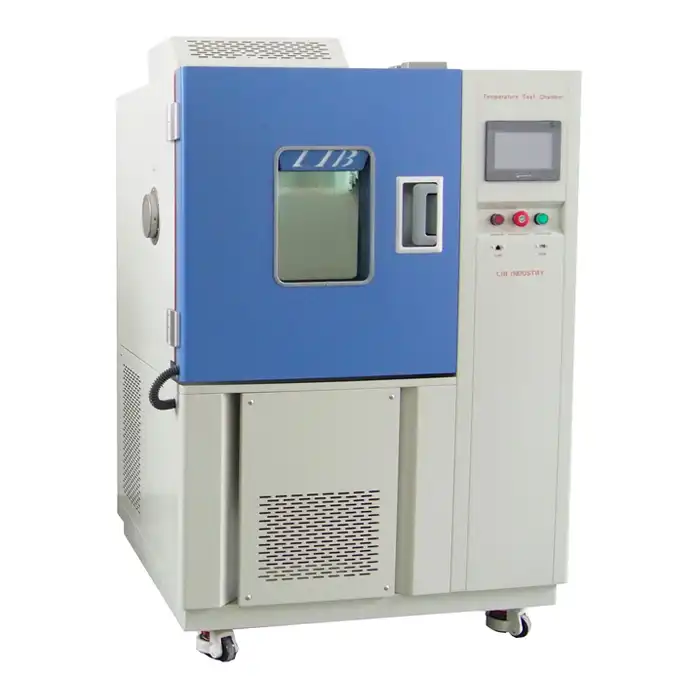
Temperature Cycling Test
Temperature cycling represents the foundational environmental stress test for photovoltaic modules, subjecting them to repeated thermal expansion and contraction cycles that mimic diurnal temperature variations experienced during field deployment. This testing reveals material incompatibilities, interconnection vulnerabilities, and encapsulation weaknesses that progressive thermal stress exacerbates.
Thermal Stress Mechanisms and Failure Modes
Photovoltaic modules comprise multiple material layers with dissimilar thermal expansion coefficients - glass superstrates, polymeric encapsulants, crystalline silicon cells, metallic interconnects, and polymer backsheets each respond differently to temperature fluctuations. During heating phases, materials expand at characteristic rates determined by their coefficient of thermal expansion (CTE). Subsequent cooling induces contraction, creating interfacial shear stresses wherever CTE mismatches exist. LIB Industry's PV environmental chamber precisely controls temperature transitions, enabling programmable ramp rates that replicate field conditions or accelerate stress accumulation through enhanced thermal gradients. Solder joints connecting cells experience fatigue crack propagation from cyclic strain, eventually causing series resistance increases or open-circuit failures. Encapsulant delamination initiates at cell edges where stress concentration peaks, progressing toward cell centers with continued cycling.
IEC 61215 Temperature Cycle Protocol Requirements
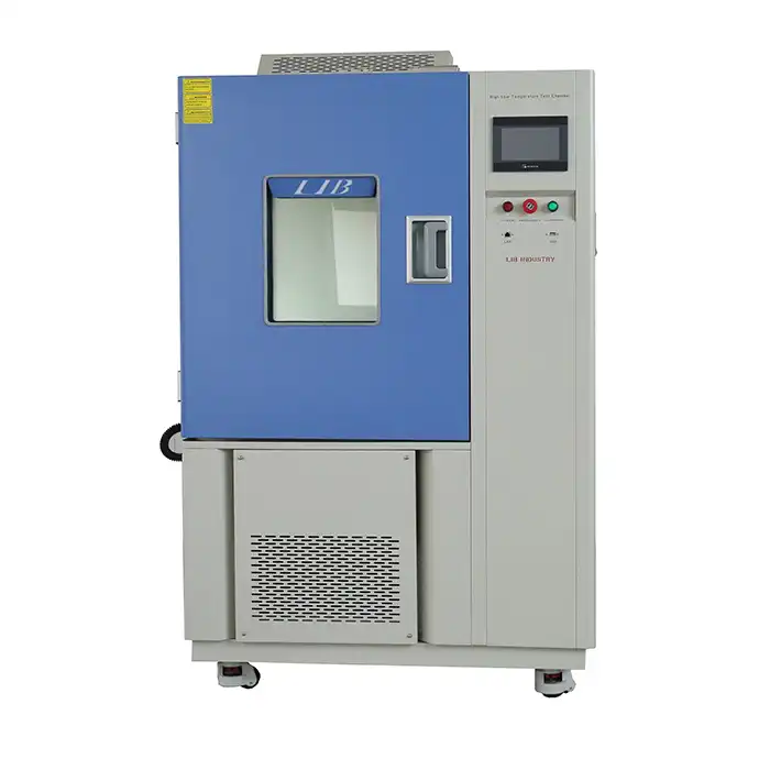
The International Electrotechnical Commission standard IEC 61215 specifies temperature cycling requirements for crystalline silicon terrestrial photovoltaic modules seeking type approval certification. This protocol mandates 200 cycles between -40°C and +85°C with specific dwell times and transition rates. Modules must reach thermal equilibrium at each temperature extreme, typically requiring 10-minute holds at setpoint conditions before transitioning. Temperature change rates should not exceed 100°C per hour during heating or cooling phases, preventing unrealistic thermal shock that field conditions would never impose. LIB Industry's PV environmental chambers achieve temperature fluctuation within ±0.5°C and deviation of ±2.0°C throughout the workspace, ensuring uniform thermal exposure across all test specimens regardless of chamber position. The PT-100 Class A sensors provide 0.001-degree resolution, enabling precise documentation of thermal profiles for certification submissions.
Extended Cycling for Enhanced Reliability Validation
Standard certification testing establishes minimum acceptable performance thresholds, while manufacturers pursuing premium market positioning often implement extended cycling protocols demonstrating superior durability. Extended tests may impose 400, 600, or even 1000 temperature cycles, revealing latent defects and marginal designs that survive standard testing but fail prematurely under field conditions. Accelerated testing employing wider temperature spans (such as -40°C to +110°C) or faster transition rates compresses equivalent field exposure into shortened laboratory timeframes. The customizable programming capabilities LIB Industry offers enable manufacturers to develop proprietary test sequences optimizing correlation between laboratory cycling and field degradation rates observed across diverse climate zones. Data logging throughout extended tests tracks resistance evolution, fill factor degradation, and power output decline, generating reliability prediction models that inform warranty terms and performance guarantees.
Table 1: Common Temperature Cycling Test Parameters
|
Test Protocol |
Temperature Range |
Cycle Count |
Ramp Rate |
Dwell Time |
Application |
|
IEC 61215 |
-40°C to +85°C |
200 cycles |
≤100°C/hr |
10 minutes |
Standard certification |
|
EC 61215 Extended |
-40°C to +85°C |
400-600 cycles |
≤100°C/hr |
10 minutes |
Premium reliability |
|
Accelerated Protocol |
-40°C to +110°C |
200 cycles |
Variable |
15 minutes |
Desert climate validation |
|
Automotive Variant |
-40°C to +90°C |
1000 cycles |
≤100°C/hr |
30 minutes |
Vehicle-integrated PV |
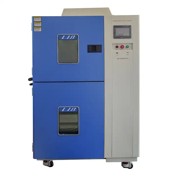
Humidity Freeze Test
Humidity freeze testing exposes photovoltaic modules to combined moisture ingress and freezing conditions that replicate climate zones experiencing humid summers followed by subfreezing winters. This evaluation methodology proves particularly relevant for modules deployed in temperate regions where seasonal transitions create demanding environmental conditions.
Moisture Penetration and Ice Formation Dynamics
Water vapor permeates polymeric encapsulants and backsheet materials through diffusion processes accelerated by elevated temperatures and humidity levels. The PV environmental chamber maintains 85% relative humidity at +85°C during moisture exposure phases, saturating permeable materials with absorbed water. Subsequent temperature reduction to -40°C causes absorbed moisture to undergo phase transition, forming ice crystals within encapsulant matrices and along material interfaces. Ice expansion generates internal mechanical stresses that exceed those from thermal expansion alone, potentially causing delamination, cell cracking, or interconnect rupture. LIB Industry's chambers achieve humidity deviation within ±2.5% RH, ensuring consistent moisture loading across specimens despite variations in chamber airflow patterns or specimen positioning.
IEC 61215 Humidity Freeze Cycle Specifications
The IEC 61215 humidity freeze test comprises 10 cycles, each consisting of specific temperature and humidity sequences designed to maximize moisture uptake followed by freeze-induced stress. Each cycle begins with an 85°C, 85% RH exposure lasting at least 20 hours, ensuring thorough moisture saturation of encapsulant materials. Temperature subsequently decreases to -40°C while humidity becomes uncontrolled (though typically diminishing as temperature drops reduce absolute moisture content). Modules dwell at -40°C for at least 4 hours, allowing complete ice formation throughout moisture-laden regions. The cycle concludes with temperature restoration to ambient conditions before initiating the next cycle. Unlike temperature cycling alone, humidity freeze testing addresses corrosion mechanisms since moisture presence enables electrochemical reactions between dissimilar metals used in cell metallization, interconnects, and junction boxes.
Long-Duration Damp Heat Exposure
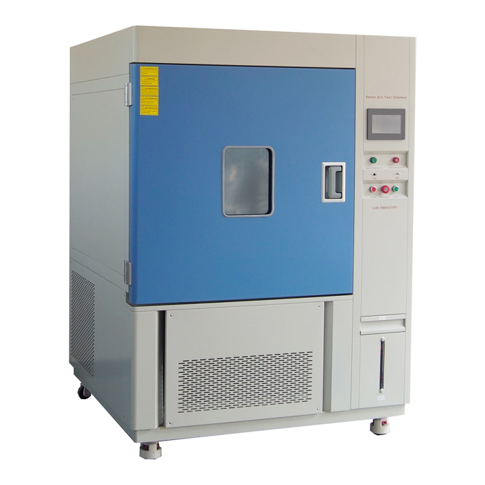
Beyond cyclic humidity freeze testing, photovoltaic modules undergo extended damp heat exposure simulating tropical deployment conditions. IEC 61215 specifies 1000 hours of continuous 85°C, 85% RH exposure without temperature cycling. This protocol accelerates moisture-driven degradation including encapsulant yellowing, adhesion loss, and corrosion of cell metallization or ribbon interconnects. LIB Industry's PV environmental chambers accommodate panels up to 2 meters in length with capacities ranging from 4 to 12 pieces simultaneously, maximizing testing throughput while maintaining environmental uniformity. The test duration capability extending to 1000 hours reflects chamber construction using corrosion-resistant materials including SUS304 stainless steel interiors that withstand prolonged humid exposure without deterioration. Automated humidity control systems continuously adjust moisture injection rates compensating for temperature variations and specimen outgassing, maintaining setpoint conditions throughout multi-week test campaigns.
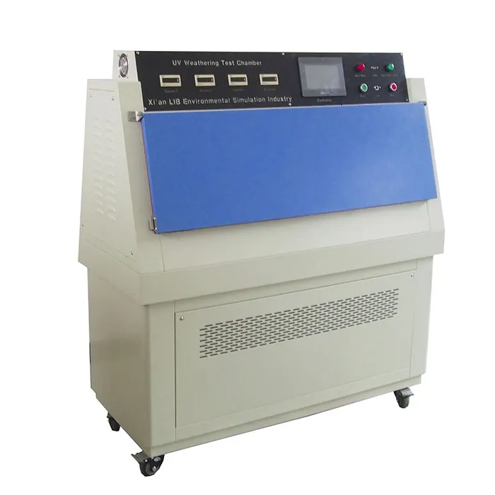
UV Exposure Test
Ultraviolet radiation represents a primary degradation mechanism for polymeric materials comprising photovoltaic module encapsulants, backsheets, and junction box components. UV exposure testing evaluates material resistance to photodegradation, embrittlement, and optical transmission losses that reduce module performance over decades of sunlight exposure.
Photodegradation Mechanisms in Polymeric Materials
Polymeric materials absorb ultraviolet photons possessing sufficient energy to break chemical bonds within polymer chains. This photolytic cleavage initiates free radical formation that propagates through oxidation reactions, progressively degrading mechanical properties and optical characteristics. Ethylene vinyl acetate (EVA) encapsulants undergo yellowing and browning as conjugated double bond systems form, reducing optical transmission and decreasing photocurrent generation. Backsheet materials including polyvinyl fluoride and polyethylene terephthalate experience surface chalking, cracking, and mechanical weakening from UV-induced chain scission. The PV environmental chamber integrates UV lamp systems generating spectral distributions matching solar radiation characteristics, with particular emphasis on the UV-A (315-400 nm) and UV-B (280-315 nm) wavelengths most damaging to polymeric materials.
IEC 61215 UV Preconditioning Test Protocol
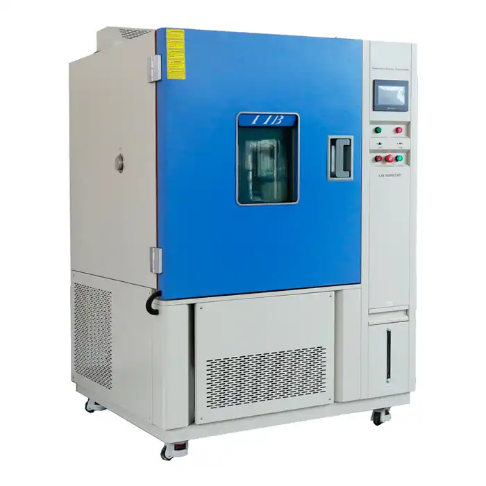
IEC 61215 specifies UV preconditioning preceding damp heat testing, exposing modules to 15 kWh/m² total UV irradiance between 280-400 nm wavelengths. This exposure level represents several months of outdoor exposure compressed into accelerated laboratory timeframes. Test protocols maintain module temperature at 60°C ± 5°C during UV exposure, replicating elevated temperatures photovoltaic modules experience during daytime operation when solar radiation peaks. LIB Industry's UV exposure systems employ precisely calibrated radiometers monitoring irradiance levels across the exposure plane, ensuring uniform UV dosage regardless of specimen position. The combination of UV exposure followed by humidity freeze or damp heat testing reveals synergistic degradation where UV-weakened materials exhibit accelerated moisture ingress or reduced adhesion strength compared to UV-unexposed controls.
Extended UV Durability Testing Beyond Certification Minimums
Manufacturers developing modules warranted for 25-30 year operational lifetimes increasingly implement extended UV exposure protocols exceeding certification minimums. Advanced testing may deliver 50-100 kWh/m² total UV dosage while incorporating temperature cycling or humidity exposure simultaneously with UV irradiation. These combined stress protocols better replicate field conditions where modules experience UV exposure, elevated temperatures, and moisture simultaneously rather than sequentially. Spectral tuning of UV sources enables evaluation under specific climate conditions - high-altitude installations experience increased UV-B intensity, while tropical regions combine high UV dosage with extreme humidity. LIB Industry's customization expertise enables integration of specialized UV lamp configurations, optical filters, and irradiance monitoring systems tailored to specific research objectives or qualification requirements beyond standard certification protocols.
Table 2: UV Exposure Test Parameters and Material Degradation Indicators
|
Test Parameter |
IEC 61215 Requirement |
Extended Protocol |
Measurement Method |
|
UV Irradiance (280-400nm) |
15 kWh/m² |
50-100 kWh/m² |
Calibrated radiometer |
|
Module Temperature |
60°C ± 5°C |
60-75°C |
PT-100 sensors |
|
Test Duration |
~240 hours @ 60 W/m² |
Variable |
Calculated from irradiance |
|
Encapsulant Yellowing Index |
Visual inspection |
Spectrophotometry |
ASTM E313 |
|
Backsheet Tensile Strength |
Not specified |
≥50% retention |
ASTM D882 |
Salt Mist Corrosion Test
Coastal deployment environments expose photovoltaic modules to salt-laden atmospheres that accelerate metallic corrosion, particularly affecting cell metallization, interconnect ribbons, and frame-to-panel grounding connections. Salt mist testing evaluates module resistance to marine environmental conditions ensuring reliable operation in seaside installations.
Corrosion Mechanisms in Photovoltaic Components
Salt deposition on module surfaces creates electrolytic pathways enabling galvanic corrosion between dissimilar metals used throughout module construction. Silver cell metallization contacts copper interconnect ribbons, establishing electrochemical potential differences that drive corrosive current flow when ionic solutions bridge the junction. Aluminum frames connected to stainless steel mounting hardware similarly create galvanic couples vulnerable to accelerated corrosion. The PV environmental chamber equipped with salt spray capabilities generates fine mist containing 5% sodium chloride solution, uniformly depositing corrosive electrolyte across module surfaces. Edge seal integrity becomes critical - inadequate perimeter sealing permits salt solution ingress directly to cell metallization and interconnects, dramatically accelerating degradation compared to well-sealed modules where corrosion proceeds only through slow moisture permeation.
IEC 61701 Salt Mist Testing Standard
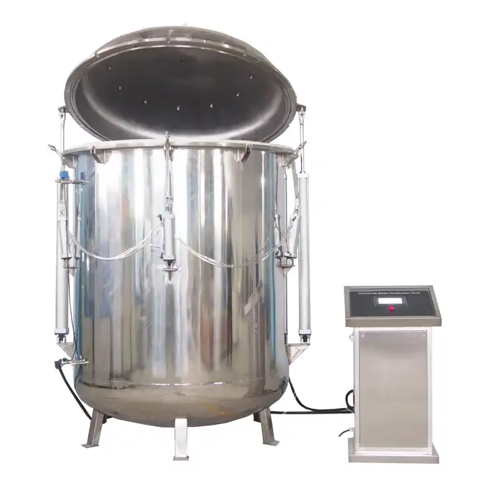
While IEC 61215 addresses general environmental durability, IEC 61701 specifically targets salt mist corrosion resistance for photovoltaic modules intended for marine or coastal deployment. This standard defines severity levels ranging from Level 1 (low salinity environments) through Level 6 (severe marine exposure). Level 2 testing - appropriate for installations within 10 kilometers of coastlines - requires 30 cycles of salt spray exposure alternating with humidity exposure and ambient drying phases. Each cycle includes 2 hours of 5% NaCl salt spray at 35°C, followed by humidity exposure at 85% RH and ambient temperature storage. Total test duration spans approximately 60 days, substantially longer than other qualification tests. LIB Industry's chambers withstand corrosive salt spray environments through glass fiber reinforced plastic construction and corrosion-resistant internal components, maintaining calibration accuracy throughout extended salt exposure protocols.
Accelerated Corrosion Testing and Failure Analysis
Accelerated corrosion testing employs enhanced salt concentrations, elevated temperatures, or UV irradiation during salt exposure to compress decades of coastal exposure into abbreviated laboratory timeframes. Combined stress protocols incorporating salt spray, humidity cycling, and UV exposure reveal synergistic degradation mechanisms where UV-induced backsheet cracking permits moisture ingress, subsequently enabling salt solution penetration to metallization layers. Post-test analysis employing cross-sectional microscopy, energy-dispersive X-ray spectroscopy, and electrical characterization identifies specific corrosion-induced failure mechanisms. Common degradation modes include silver metallization dissolution, copper interconnect oxidation, and aluminum frame pitting. Understanding these mechanisms informs design modifications such as enhanced edge sealing, alternative metallization systems, or protective coatings that improve marine environment durability. LIB Industry's versatile chamber configurations accommodate both standard salt spray testing and custom corrosion protocols developed by manufacturers pursuing superior coastal performance.
FAQ
How long does a complete IEC 61215 qualification test sequence typically require?
The complete IEC 61215 test sequence spans approximately 90-120 days depending on chamber availability and scheduling. Temperature cycling requires about 2-3 weeks, humidity freeze testing needs 2 weeks, damp heat exposure demands 6 weeks, and UV preconditioning takes roughly 10 days. Additional tests including mechanical load, hail impact, and electrical safety add further duration to comprehensive qualification campaigns.
Can different photovoltaic module technologies share the same environmental chamber during testing?
Yes, crystalline silicon, thin-film, and emerging photovoltaic technologies can undergo testing in the same PV environmental chamber provided dimensional compatibility exists and cross-contamination risks remain negligible. LIB Industry's chambers accommodate panels up to 2 meters length with adjustable shelving systems supporting diverse module configurations. Scheduling protocols ensure adequate cleaning between test campaigns when testing dissimilar technologies.
What maintenance requirements do PV environmental chambers demand for sustained accuracy?
Regular calibration verification of temperature and humidity sensors ensures continued measurement accuracy, typically performed annually by certified metrology laboratories. UV lamp systems require periodic radiometer verification and lamp replacement as output intensity degrades. Salt spray nozzles need cleaning to prevent clogging, while chamber seals undergo inspection for maintaining environmental isolation. LIB Industry provides comprehensive maintenance protocols and replacement component availability supporting long-term chamber operation.
Ensure Module Reliability with LIB Industry
LIB Industry delivers turnkey PV environmental chamber solutions tailored to your photovoltaic testing requirements. As a leading manufacturer and supplier, we provide complete testing systems from design through commissioning, installation, and operator training. Our customizable chambers accommodate diverse panel sizes with precision environmental control ensuring certification compliance and reliability validation. Contact our specialists at ellen@lib-industry.com to discuss your photovoltaic testing needs.

.webp)