How to Conduct Thermal Cycling Test Chamber Evaluation for Solar Panel Performance Stability?
Photovoltaic (PV) modules are expected to operate continuously in extreme outdoor environments for 25 to 30 years. Over their operational life, solar panels face relentless daily and seasonal temperature fluctuations—ranging from sub-zero night freezes to daytime surface temperatures exceeding 80°C. These severe thermal swings induce continuous mechanical expansion and contraction across the interconnected layers of the module.
Without rigorous testing, repeated thermal stress leads to solder joint fatigue, cell micro-cracking, encapsulant delamination, and sudden electrical power loss. To prevent field failures, protect manufacturer warranties, and meet bankability standards, engineering teams rely on a Thermal Cycling Test Chamber. This equipment compresses years of field thermal fatigue into weeks of controlled, accelerated laboratory testing.
This technical guide provides solar engineering managers, quality control directors, and procurement specialists with a comprehensive breakdown of thermal cycling mechanisms, international standards (IEC 61215 / IEC 61730), test parameters, equipment selection, and turnkey solutions from LIB Industry.
Thermal Stress & Degradation Mechanisms in Photovoltaic Modules
_1773978265968.jpg "blog-1-1") A solar panel is a multi-layer composite structure made of glass, polymer encapsulants (EVA/POE), silicon wafers, copper interconnect ribbons, lead/tin solder, and a polymer backsheet. Because each material possesses a different Coefficient of Thermal Expansion (CTE), rapid temperature changes generate intense shear stresses at material interfaces.
A solar panel is a multi-layer composite structure made of glass, polymer encapsulants (EVA/POE), silicon wafers, copper interconnect ribbons, lead/tin solder, and a polymer backsheet. Because each material possesses a different Coefficient of Thermal Expansion (CTE), rapid temperature changes generate intense shear stresses at material interfaces.
PV Module Multi-Layer CTE Comparison
| Layer | Material | CTE (×10⁻⁶ / K) | Relative Level |
|---|---|---|---|
| Front Cover | Glass | ~8.5 | Low |
| Encapsulant | EVA / POE | ~100–200 | High |
| Solar Cell | Silicon | ~2.6 | Low |
| Interconnect | Copper Ribbon | ~16.5 | Medium |
| Back Layer | Backsheet Laminate | ~30–80 | Medium–High |
1. Coefficient of Thermal Expansion (CTE) Mismatch
When a module heats up, the polymer encapsulant expands at a rate up to 50 times faster than the underlying silicon wafer. This severe expansion mismatch puts extreme mechanical tension on the busbars and cell edges, leading to delamination and moisture ingress pathways over time.
2. Solder Joint & Interconnect Ribbon Fatigue
Copper ribbons connecting individual cells flex with every temperature swing. Hundreds of thermal cycles cause work-hardening of the solder interface, leading to micro-void formation, solder joint cracking, and increased series resistance , which degrades maximum power output ($P_{\text{max}}$).
3. Degradation Summary Matrix
| Material Layer | Primary Thermal Stress Effect | Field Failure Consequence | Primary Diagnostic Method |
|---|---|---|---|
| Silicon Cells | Differential strain from adjacent layers | Micro-crack formation, isolated cell fragments | Electroluminescence (EL) Imaging |
| Solder Joints | Cyclic shear bending on interconnect ribbons | Ribbon fatigue, open circuits, rising series resistance | I-V Curve Tracing / Flash Testing |
| Encapsulant (EVA/POE) | Temperature-dependent stiffness changes | Delamination, bubble formation, moisture pathways | Visual Inspection / Colorimetry |
| Frame & Backsheet | Mismatch expansion relative to glass | Sealant breakdown, edge delamination, insulation loss | Wet Leakage & Ground Continuity Test |
Key Takeaway: Solder joint fatigue and micro-cracking accumulate quietly without initial visible symptoms. Accelerated thermal cycling is the most reliable way to expose structural weaknesses before solar modules enter mass production.
Testing Standards & Technical Methodology (IEC 61215 & Beyond)
Compliance with international testing frameworks validates solar panel design durability and unlocks commercial distribution worldwide.
Core PV Qualification Standards
| Standard | Purpose | Cycle Requirement | Focus Area |
|---|---|---|---|
| IEC 61215 | Design Qualification & Approval | TC200 (200 cycles), <5% power degradation | Module performance & durability |
| IEC 61730 | PV Module Safety Qualification | Paired with IEC 61215 | Electrical insulation & frame integrity |
| Extended Programs | Enhanced Bankability Validation | TC400 / TC600 | Long-term wear-out reliability |
Decoding IEC 61215 Thermal Cycling Protocol (TC200)
The standard baseline test for crystalline silicon and thin-film modules is the TC200 cycle under IEC 61215:
Temperature Range: -40°C (±2°C) to +85°C (±2°C).
Cycle Count: 200 complete thermal cycles.
Ramp Rate: Maximum heating and cooling rate of 100°C per hour (approx. 1.67°C to 3.33°C per minute); high-rate stress cycles can reach 5°C to 15°C per minute.
Dwell Time: Minimum dwell time of 10 minutes at extreme high (+85°C) and low (-40°C) temperatures.
Current Injection: During the heating cycle from 25°C to +85°C, peak operational current ($I_{\text{mp}}$) is injected into the module to simulate actual electrical and thermal working loads.
Single Cycle Phase Breakdown
| Phase | Temperature Target | Action | Notes |
|---|---|---|---|
| 1. Ramp Up | 25°C → +85°C | Heating at rated ramp rate | Peak current ($I_{\text{mp}}$) injected during this phase |
| 2. High Dwell | +85°C | Hold temperature | Minimum 10-minute dwell |
| 3. Ramp Down | +85°C → -40°C | Cooling at rated ramp rate | No current injection |
| 4. Low Dwell | -40°C | Hold temperature | Minimum 10-minute dwell |
| 5. Repeat | — | Return to Phase 1 | Repeated for 200 (or 400/600) total cycles |
Standards Parameter Comparison
| Standard / Protocol | Focus & Purpose | Temperature Range | Total Cycle Count | Key Pass/Fail Criteria |
|---|---|---|---|---|
| IEC 61215 (TC200) | Baseline Design Qualification | -40°C to +85°C | 200 Cycles | $P_{\text{max}}$ loss < 5%; no major visual defects; wet insulation pass |
| IEC 61730 | Safety & Insulation Integrity | -40°C to +85°C | Paired with IEC 61215 | No electrical shock hazard or frame dielectric breakdown |
| Extended TC400 / TC600 | Bankability & Wear-Out Testing | -40°C to +85°C | 400 to 600 Cycles | Identifies late-stage fatigue; satisfies project financier requirement |
Equipment Selection Guide: Reach-In Chambers vs. Walk-In Thermal Rooms
Choosing the right thermal cycling equipment depends on test volume, module dimensions (60-cell, 72-cell, or large-format utility panels), and required throughput.
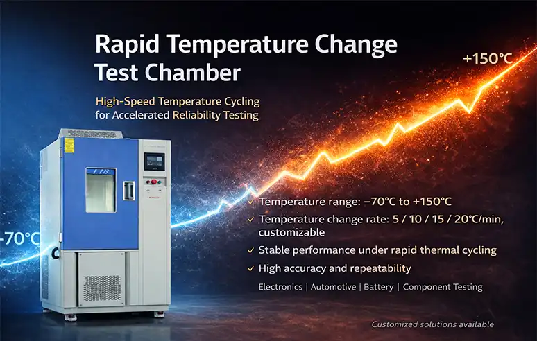
Chamber Configuration Overview
| Configuration | Volume | Best Suited For | Ramp Rate |
|---|---|---|---|
| Box / Reach-In Chamber | 1,000L – 3,000L | Mini-modules, R&D batches, 2–6 standard PV modules | Rapid, up to 15°C/min |
| Walk-In Thermal Cycling Room | Custom, >10 m³ | Full-size commercial arrays, high-volume production, multi-rack batch validation | 3°C/min – 8°C/min |
Feature Comparison Matrix
| Equipment Parameter | Reach-In Thermal Cycling Chamber | Walk-In Thermal Test Room |
|---|---|---|
| Internal Capacity | 1,000 Liters – 3,000 Liters | 10 m³ to 60+ m³ (Customizable) |
| Specimen Capacity | 2 to 8 full-size solar panels | 20 to 50+ full-size solar panels per run |
| Temperature Range | -70°C to +150°C (Standard PV: -40°C to +85°C) | -40°C to +95°C |
| Ramp Rate Capability | 5°C/min, 10°C/min, or 15°C/min | 3°C/min to 8°C/min |
| Current Injection Interface | Integrated multi-channel DC power leads | Centralized power distribution panel with rack monitoring |
| Footprint & Installation | Compact unit; fits inside standard lab space | Dedicated facility floor space with external machinery housing |
LIB Engineering Expertise & Photovoltaic Test Solutions
Selecting high-precision environmental testing equipment requires an experienced manufacturing partner capable of delivering reliable long-term support.
About LIB Industry
Established in 2012, Xi'an LIB Environmental Simulation Industry is a specialized designer, manufacturer, and global provider of environmental test chambers. LIB delivers complete turnkey testing solutions—from initial laboratory planning and engineering customization to delivery, installation, operator training, and calibration.
Comprehensive Product Range: LIB engineers a full suite of environmental test chambers, including thermal cycling chambers, damp heat chambers, UV/xenon weathering test chambers, dust and water ingress test equipment, salt spray chambers, and large walk-in environmental rooms.
One-Stop Turnkey Service: LIB manages every phase of equipment integration, providing hassle-free setup and rapid deployment for testing laboratories worldwide.
Industry-Leading Support: All LIB systems include a 3-Year Complete Warranty and Lifetime Technical Support & Service, safeguarding your testing facility investment over the long term.
Core Technical Features of LIB Solar Thermal Chambers (TR Series)
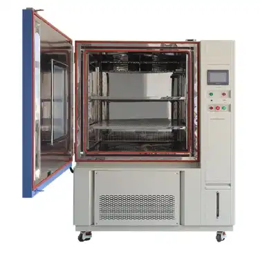
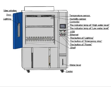
LIB TR Series Thermal Cycling Test Chambers are engineered specifically to meet IEC 61215 and IEC 61730 requirements:
 |
 |
 |
 |
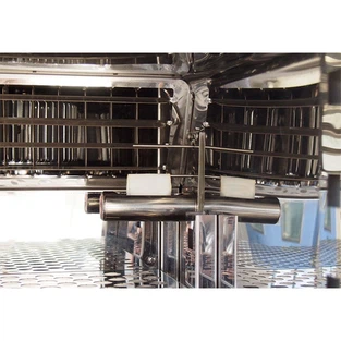 |
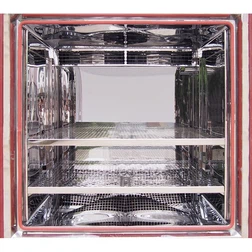
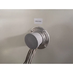
| Robust Workroom | Cable Hole | Temperature and Humidity Sensor |
Precision Temperature Control: High-output nichrome heating elements paired with a French Tecumseh/Bizter cascade refrigeration system ensure stability within ±0.5°C.
Programmable Ramp Rates: Configurable heating and cooling speeds (5°C/min, 10°C/min, or 15°C/min) allow seamless transition between standard IEC qualification and accelerated internal stress protocols.
Uniform Airflow Circulation: Heavy-duty centrifugal fan systems prevent thermal stratification across large 72-cell or N-type TOPCon panels.
Integrated Current Injection Module: Built-in multi-channel DC power supply interfaces automatically inject peak operating current during heating cycles as required by IEC 61215.
Comprehensive Data Logging: Programmable touchscreen controllers with Ethernet/USB export log continuously for full compliance auditing and certification submissions.
Real-World Customer Case Study & Field Verification
Project Background
A Tier-1 solar module manufacturer developing high-efficiency N-type TOPCon utility-scale panels required in-house thermal cycling capability to achieve extended TC400 and TC600 bankability credentials for utility project financiers.
The Solution
LIB Industry custom-engineered and delivered a TR-1000 Large-Capacity Thermal Cycling Chamber equipped with custom vertical racking fixtures, high-speed cascade cooling, and multi-channel current injection ports.
LIB Field Implementation Workflow
| Step | Task |
|---|---|
| 1 | On-Site Installation & Positioning at PV QC Facility |
| 2 | Temperature Uniformity Calibration Across 8 Full-Size Panels |
| 3 | Automation Setup for IEC 61215 TC400 Program & Current Injection |
| 4 | Operator Training on Controller Programming & Data Logging |
| 5 | Final Sign-off & 3-Year Warranty Activation |
During commissioning, LIB engineers conducted multi-point temperature mapping across all sample panels, ensuring temperature deviation remained strictly under ±1.0°C across the entire 2,000L internal volume.
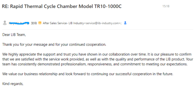
Customer Feedback: "LIB's thermal cycling chamber allowed us to perform TC400 and TC600 bankability tests completely in-house. The uniform airflow and precise ramp rate control helped us optimize our solder paste chemistry and ribbon dimensions before mass production, cutting our third-party certification timelines by nearly two months."
Related Products from LIB Industry
Thermal cycling is only one part of a full PV module qualification program under IEC 61215 / IEC 61730. LIB Industry also manufactures the complementary environmental test equipment needed to complete a full sequential test flow:
| Product | Typical Use Case | Related Standard |
|---|---|---|
|
|
Long-duration 85°C / 85% RH exposure to evaluate encapsulant and backsheet moisture resistance | IEC 61215 (Damp Heat, DH1000) |
|
|
Simulates years of solar UV exposure to test encapsulant yellowing, backsheet degradation, and material embrittlement | IEC 61215 (UV Preconditioning) |
|
|
Evaluates corrosion resistance of frames, mounting hardware, and junction box connectors, critical for coastal and marine installations | IEC 61701 |
|
|
Verifies junction box and connector sealing against dust intrusion and water jets/immersion | IEC 60529 (IP65/IP67/IP68) |
|
|
Combines temperature, humidity, and mechanical load testing for full-size module or utility-scale array batches | IEC 61215 / IEC 61730 (combined sequence testing) |


Recommendation: Many manufacturers pair the TR Series Thermal Cycling Chamber with a Damp Heat Chamber and UV Weathering Chamber to run the complete IEC 61215 sequential test flow (Thermal Cycling → Humidity Freeze → Damp Heat → UV Preconditioning) in-house, reducing dependence on third-party labs and shortening certification timelines.
Contact LIB Industry to discuss a combined equipment package tailored to your full qualification test sequence.
Frequently Asked Questions (FAQs)
Q1: How many thermal cycles are required for standard IEC 61215 certification?
IEC 61215 requires 200 cycles (TC200) between -40°C and +85°C. However, many manufacturers now test up to 400 or 600 cycles (TC400 / TC600) to demonstrate extended reliability and earn bankability approval from major project financiers.
Q2: Why is current injected into solar modules during the heating phase of the test?
Injecting current ($I_{\text{mp}}$) while the temperature rises from 25°C to +85°C simulates real-world operating stress. The electrical current generates localized internal Joule heating in cell ribbons and solder points, matching the combined thermal-electrical stress a module experiences under direct sunlight.
Q3: What is the acceptable maximum power degradation after thermal cycling?
Under IEC 61215, a solar module passes the thermal cycling test if its maximum power output ($P_{\text{max}}$) degrades by less than 5% compared to its pre-test baseline, provided it also passes visual inspection and wet insulation testing.
Q4: Which non-destructive testing tools are used to check modules after thermal cycling?
Electroluminescence (EL) imaging is the primary tool used after thermal cycling. EL imaging applies a small current to the panel in a dark room, emitting infrared light that clearly exposes dark spots, micro-cracks, and broken cell interconnections invisible to the human eye.
Q5: What ramp rate should I choose for my thermal cycling chamber?
Standard IEC 61215 qualification testing requires a ramp rate under 100°C/hour (approx. 1.67°C/min). However, selecting a chamber capable of 5°C/min, 10°C/min, or 15°C/min gives engineering teams the flexibility to run rapid R&D screening tests and accelerate production screening.
Upgrade Your PV Module Reliability Testing with LIB Industry
Accelerated thermal cycling is the cornerstone of solar panel quality assurance. By transforming decades of thermal stress into weeks of actionable laboratory data, manufacturers can verify module durability, protect warranty commitments, and build confidence with global project lenders.
Ready to Optimize Your Testing Facility?
Contact LIB Industry today to consult with our environmental testing specialists, receive technical specifications, or request a custom quote tailored to your solar module testing program.
Email: ellen@lib-industry.com
Services Provided: Free Technical Consultation, Custom Chamber Design, On-Site Installation, Calibration, 3-Year Warranty, Lifetime Technical Support.